Wanderlodge: Kohler Slip Ring Replacement
Note: This guide pertains to slip ring replacement & general R&R on a Kohler generator, model 12.5cc, spec 135010,
as mounted in a 1986 Blue Bird Wanderlodge PT-40. This information is provided as-is, with no guarantees as to
accuracy or suitability to any purpose. Use at your own risk.
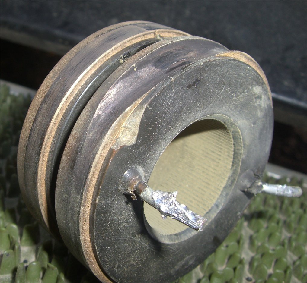 Inside your generator are a pair of brushes which ride on top of a slip ring. Eventually, that slip ring wears out and starts to look a bit like the one above. You can clearly see the deep groove in the rear ring; this causes brushes to be used up rapidly. I'd installed a new set of brushes, only to have them fail within just a few hours of run time. So I consulted my fellow Wanderlodge owners and they pointed me in the right direction. The generator can be repaired with 8 to 10 hours of work and about a hundred bucks in parts, without removing it from the coach. Or, you can take it to a repair shop and hand over $1,500 - $2,000 for the same job. Being a person who tries not to throw money at a problem if I don't have to, I opted to fix it myself. Get yourself the following list of parts from your local Kohler dealer:
Total expense, about a hundred bucks (June 2008). Please note, the slip ring (collector ring) has been changed slightly. The new assembly has a key notch in the shaft hole, which I'm told is to route wires through on another model of generator. My old slip ring did not have this notch, which caused a good deal of confusion. The new part is perfectly compatible with the old, don't worry about the key notch, just pretend it isn't there. One additional point of confusion was the old assembly came off with grooves in the shaft hole, which corresponded to splines on the shaft. I expected the new ring would need to "line up" with these splines, much like installing a transmission. When the new assembly didn't have the corresponding grooves, I assumed it was a problem. This is not the case. The grooves are put into the ring by the shaft when you install it. The shaft splines dig into the softer ring material to hold it in place. So, don't let the lack of grooves on your new ring worry you. Tools needed to perform this job include:
Slide the generator out as far as it will go, then disconnect the positive battery terminal from the genset. I also flipped the main generator circuit breaker off since the coach was plugged into shore power. Perhaps unnecessary, but this eliminate any possibility of voltage coming back through the generator power feed and setting me on fire. Now, block the coach up so it won't crush you and climb under there. If you're a small person like me, you should be able to literally sit up inside the generator compartment, on the right side of the hydraulic slide shaft. This is much more comfortable than laying on your back and makes the job much easier. Now remove the four screws holding the back cover on and you should see this: 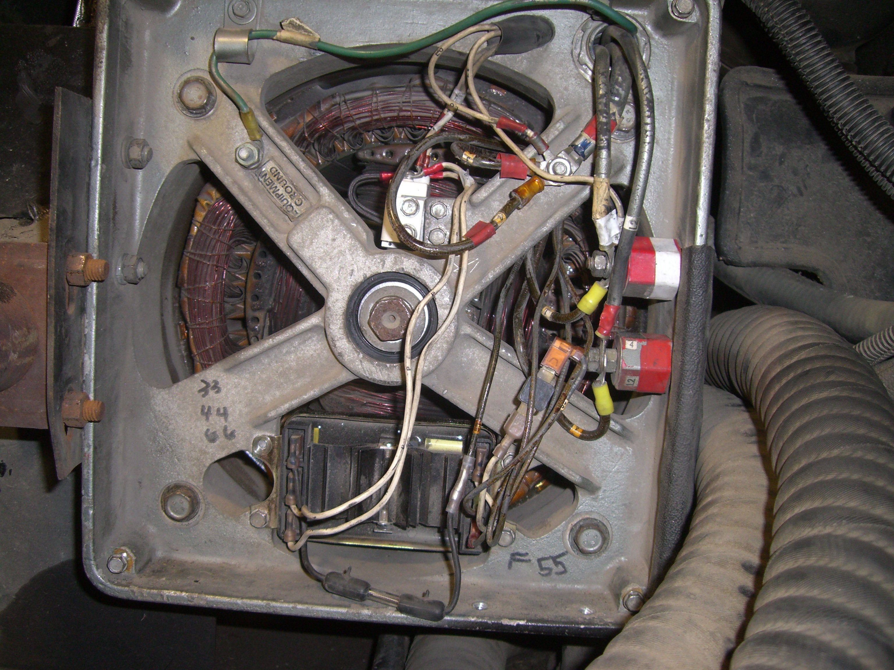 Before you do anything, mark the wires and/or take pictures. You're going to disconnect all of these and you don't want to screw it up when you put it back together. Now, disconnect all of the wires and get the stuff out of the way. Your voltage regulator is the big box on the bottom. Remove it. Your brushes are the little white box above the main generator shaft. That gets to come off, too. Likewise for the two relays (?) protruding out the right side of the generator, and both of the ground wire studs. Don't forget the bolts (one of them with a ground wire attached) on top, bolting the top plate that holds the generator's control box to the end cap. When you've removed all of the wires, it's time to get this rear generator cap off (that's the big square thing you've been removing wires and bolts from). Un-bolt the exhaust mount from the left side (four bolts, two on the exhaust, two in the end cap) and set the mounting plate aside. I always put the bolts back in objects I remove so I don't lose track of what goes where. Now, remove the four large bolts on the four corner of the end cap. These suckers are a couple of feet long and extend to the front of the generator. Those bolts not only hold that rear panel on, they hold the whole darn thing together. You're probably going to find that the square end cap piece doesn't want to come off. Get yourself a long socket extension, go around front, slip it through so it's pushing against one of the rear end cap corners and tap that sucker a couple of times with a rubber mallet. Do each of the four corners, alternating diagonally. If it's being stubborn, switch up to a hammer. Once the end cap comes off, it's going to look something like this: 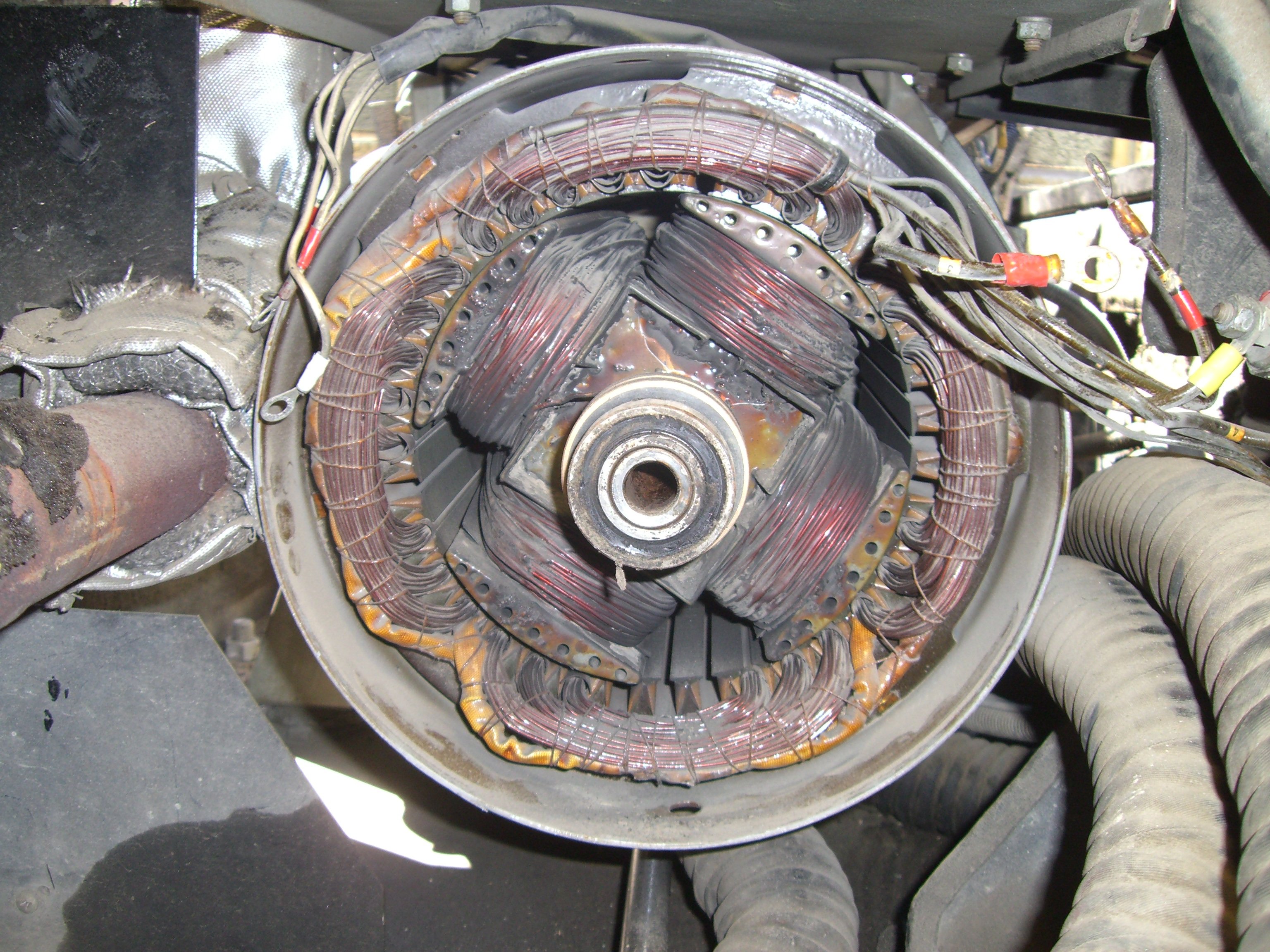 Remove the center bolt on the main shaft (already done in this picture), then use a pulley remover to take the bearing off. Since the center of the shaft is hollow, you'll need something for the pulley remover to press against. I used a socket. Be careful that your socket is big enough, you don't want to enlarge the end of that shaft by pressing a too-small socket into it with your pulley remover. It also has to be small enough to let the bearing come off, and to "catch" the center of the pulley remover in the part that normally attaches to your wrench. Just try a few difference sizes until you find one that works. With the bearing off, get yourself at least a 100 watt trigger style soldering iron (mine has a little light on the front - real handy - you can get these cheap just about anywhere), then carefully de-solder the two leads from your old slip rings. I used a flat head screwdriver to push against the wire while I heated it with the soldering iron. Once it got hot enough, it just slipped right off. Before you remove the thing (again with the pulley remover), make damn sure you know which lead goes where! Mine happened to be stopped straight up and down, so I bent the top pin straight up to ID which pin was which.  (Close-up of generator shaft, bearing & slip rings) We call them "slip rings", but it's really one piece. Don't try to separate them with your pulley remover, grab from the back of the whole assembly. When you get them out, use a continuity tester (multimeter) to determine which lead on your new one needs to go where. One wire goes to the rear ring, one goes to the front. Test the old one, then line the new one up to match. You don't want to screw this up. Line the new one up on the shaft so the wires from the generator coils will reach to the correct ring stud, then use your hands to press it on just enough so it stays. Now, get yourself a minimum 1.25" socket (you might even use a 1.5" if you have one; I didn't), slip the socket end over the shaft so it's pressing on the slip ring, then use a hammer to tap the back end of the socket until the new slip rings are snug and firm as far deep as they can go. Your shaft should be tapered, so just butt the slip ring up against the thicker shaft wall. Don't skimp and do this with a 1" socket because you don't have anything bigger, it fits on the shaft just fine but it's too close to the inner wall of the slip ring and will eat away at the ring. I only got a couple of taps in before thinking better of it. I originally tried to tap this in with a piece of schedule 40 PVC, but no go, the PVC absorbs too much of the hammer blow. Once I switched to the socket it went fast. A very short piece of pipe would also work but I'd be afraid of it being too thin and damaging the slip ring. Once you get it in, solder the leads back on. The bearing will go on easy, just tap it in with your rubber mallet. Your "Ring, tolerance", is a little metal "strap" looking thing with ridges on it. It's actually sitting on top of the bearing in the picture above. This thing slips into the generator end cap, around where the bearing will seat when the cap is re-installed. I can only assume it grips the bearing somehow. You'll see the old one in there, just put the new one in the same spot. Now, it's time to put the end cap back on. When I went to do this, mine wasn't fitting properly. I had it on there tight but it was a good half-inch back from the holes on the little tray above the generator (where the control box sits). What the heck? I figured the four big bolts would snug it up but when I went to install them, the bottom ones wouldn't go in at all. Couldn't even get them to fit in the holes. Turned out, the main generator housing is loose when you remove those bolts. When I pounded the rear end cap off, I also shifted the main housing back, so it was sagging at a slight angle. Couldn't even tell until I tried to put those bolts back in. So, I had a buddy line up the left side bottom bolt with the hole while I squatted up inside the generator compartment, from underneath, and lifted up on the generator body with all of my strength. This shifted things enough to get that bolt in. Did the same thing for the bottom right. The top ones go in easy. Then, snug them up in a criss-cross pattern, and everything lined back up. Do be careful that the outside generator body is still aligned properly: There is a hole in the bottom of the casing at the rear, where the square end cap goes on. I'm pretty sure that's a drain hole in case water gets up in there. Make sure it's pointing down. At one point during installation, mine shifted at least 5 to 10 degrees off center and I had to rotate it back. So watch that. The rest of this job is a piece of cake, assuming you did your homework before you ripped all those wires out: Just put them all back together. Last thing to watch, when you slide the generator back in, keep an eye on the hoses and on the exhaust. If you've shifted your coolant lines, they might get pinched going back in. Also, the exhaust needs to line up with the rest of the exhaust system. Mine took some adjusting to get it right. Good luck, and feel free to contact me if you get in a bind! Special thanks to Ralph Fullenwider for his advice during this project! Without Ralph's advice, I would not have attempted this and this guide would not have been created. |